Decoding the Part Number (The Prefix Logic)
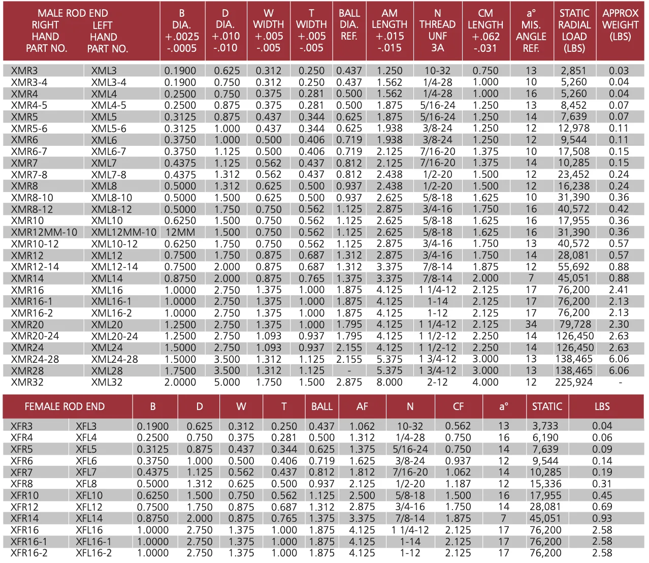
Using the SYZ XM-Series chart as a reference, the rod end part number tells you the “Gender” and “Handedness” of the joint before you even look at the numbers.
- XMR / XML: “M” stands for Male. “R” is Right-Hand (clockwise to tighten), “L” is Left-Hand (counter-clockwise).
- XFR / XFL: “F” stands for Female. These feature internal threads instead of a shank.
- The Number Suffix: Often denotes the bore size in 16ths of an inch. For example, an XMR12 has a 12/16″ (or 3/4″) bore. An XMR8-10 indicates an “oversized” shank (5/8″ thread with a 1/2″ bore).
Understanding Geometry and Tolerances
Heim joints are precision instruments. The small numbers at the top of the columns (e.g., +.0025 / -.0005) are tolerances—the acceptable margin of error from the factory.
- B (Bore Diameter): This is the internal diameter of the ball. It must match your mounting bolt. A tolerance of +.0025″ ensures a smooth “slip fit” for a standard Grade 8 bolt.
- D (Head Diameter): The total width of the circular housing. You must check this against your bracket or knuckle clearance; if the “D” is too large, the joint will hit the bracket before it can rotate.
- W (Ball Width) vs. T (Housing Width): The ball is always wider than the housing. The “W” determines your mounting spacer width, while “T” (Head Width) determines the overall clearance inside your bracket.
- Ball (Ball Diameter Ref.): The actual size of the sphere inside. A larger ball diameter usually translates to higher surface area and better load distribution.
Shank, Threads, and Length
For builders, the “N” and “AM/AF” columns are critical for calculating link length.
- N (Thread Size): Listed as a size and pitch (e.g., 3/4-16). The UNF 3A indicates a high-precision aerospace-grade thread class for a tighter fit.
- AM / AF (Length): This is the “Center-to-End” length—measured from the center of the ball to the very end of the shank. This is the number you use to calculate your tube length.
- CM / CF (Thread Length): The amount of usable thread on the shank. Remember the 1.5x rule: you should always have at least 1.5 times the shank diameter threaded into your tube adapter.
Performance Metrics
The final columns define the physical limits of the joint.
- a° (Misalignment Angle): The maximum degree the ball can tilt before the bolt hits the housing. For the XMR12, this is 14 degrees. If your suspension cycles further than this, you must switch to High-Misalignment spacers.
- Static Radial Load (LBS): The “Breaking Point.” This is the maximum force the joint can take along its shank before it deforms or snaps. An XMR16 (1″ bore) is rated at 76,200 lbs, providing a massive safety margin for heavy-duty racing.
Related reading: Heim joint size chart: metric and inch specifications · Load ratings explained: static radial vs. axial capacity · How to calculate the required load rating for your application