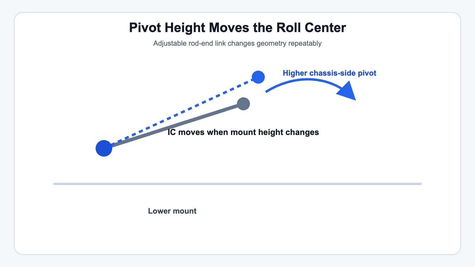
Moving the mounting height of a suspension link‘s rod end — at the chassis side, the knuckle side, or both — shifts that side’s instant center, which in turn moves the roll center up or down. That’s the entire mechanism behind roll-center tuning on a rod-end-equipped suspension. (If "instant center" and "roll center" aren’t already familiar terms, start with the concept explainer — this article assumes that baseline and goes straight to the practical adjustment.)
Where This Shows Up on a Real Rig
On off-road and street-performance builds using rod ends, roll-center adjustment usually happens at one of three points:
- Three-link and four-link suspension arms — moving an upper or lower link’s mounting hole (or its rod-end height, on a threaded adjustable link) changes that arm’s angle and therefore the instant center it produces.
- Roll center adjuster (RCA) style spacers — a spacer block or extended ball joint that relocates the lower control arm’s outer pivot point relative to the knuckle, common on lowered street-performance builds.
- Panhard bar mounting height — moving where a Panhard bar attaches to the frame or axle changes the suspension’s roll center on solid-axle setups; that’s a big enough topic on its own that it’s covered separately rather than repeated here.
The Direction of the Adjustment
As a general pattern on double-wishbone and multi-link suspensions: lowering the outer pivot relative to the inner one (or raising the inner pivot relative to the outer) angles the link so its extended centerline crosses higher — raising the instant center, and with it, the roll center. Reversing that relationship lowers both.
Treat this as the common case, not a universal formula — the exact direction depends on your specific suspension type (double wishbone, MacPherson strut, multi-link, or solid axle each behave differently), and the only way to be certain on a given rig is to plot it in CAD or measure the result directly after a test adjustment.
A real, productized example of this exact mechanism: aftermarket Roll Center Adjusters (RCAs) for Subaru MacPherson-strut front suspensions work by bolting a spacer between the lower control arm and the knuckle, which relocates the lower ball joint downward. That restores the control-arm angle closer to its factory position after lowering the car, which pushes the roll center back up toward where it started. Kits are commonly sold in a few standard drop increments — for example, roughly 10 mm for a 0.75–1.25 in. lowering, 15 mm for 1.25–1.75 in., and 20 mm for 1.75–2.5 in. That sizing table describes one category of commercial kit, not a universal engineering formula — it exists because a specific ride-height drop predictably moves the roll center by a specific amount on that particular suspension design, and the aftermarket has standardized around common increments.
Reading the Result: What Moving the Roll Center Actually Changes
Raising the roll center shortens the roll moment arm (the vertical gap between roll center and center of gravity), which reduces body roll and speeds up the car’s geometric weight transfer — the portion of load transfer that happens instantly through the suspension links rather than gradually through spring compression. That’s a different mechanism from stiffening a sway bar, even though both reduce visible body lean.
Front-to-rear roll center relationship is a genuine tuning lever for handling balance:
- Raising the front roll center relative to the rear increases front geometric weight transfer and tends to push the car toward understeer.
- Raising the rear roll center relative to the front does the same at the rear axle, tending toward oversteer.
This is a real, independent adjustment axis from sway-bar stiffness — the two work through different physical mechanisms (geometric vs. elastic weight transfer) even though both move the same needle on how the car feels mid-corner.
Where to Start
There isn’t a single correct roll center height, but there’s a commonly cited starting range: for non-aero vehicles, a roll center between roughly 15% and 30% of the center-of-gravity height is a reasonable place to begin tuning from. Treat that as an experienced motorsport-tuning rule of thumb, not a regulatory or manufacturer spec — it’s a starting point to test and adjust from, not a target to hit and stop.
After You Adjust: Don’t Skip the Alignment
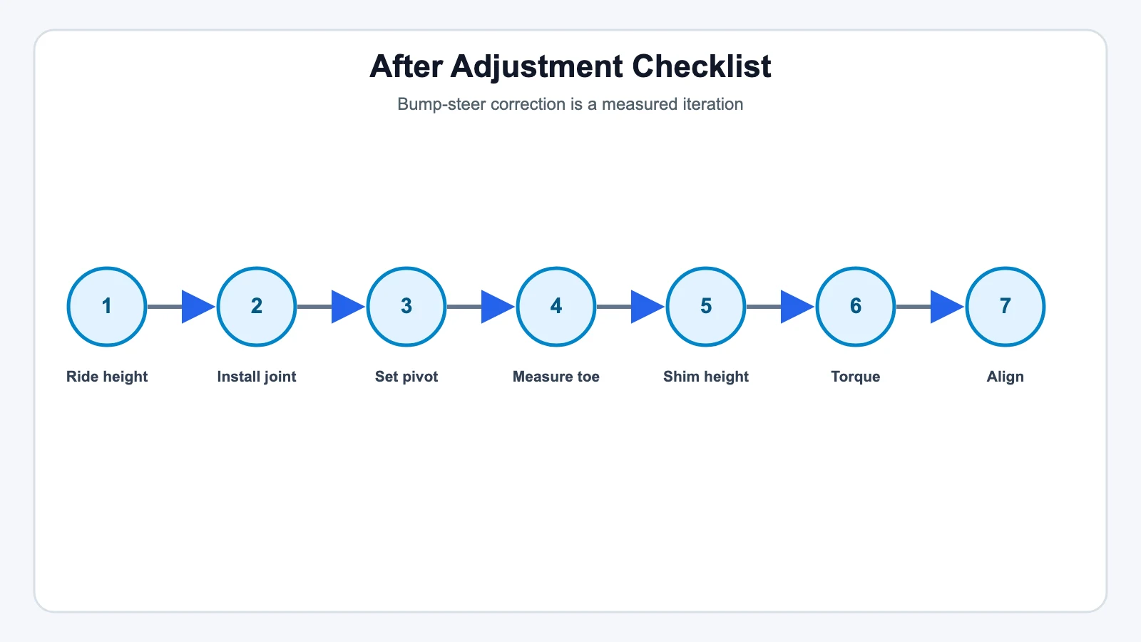
Any change to a link’s mounting height that moves the roll center also changes toe and camber curves — that’s an unavoidable side effect of the same geometry doing double duty. Two follow-up steps aren’t optional:
- Full alignment check. Static camber and toe will have shifted even if you only touched one pivot point.
- Bump steer verification. If the adjustment touched anything connected to the steering linkage, re-check bump steer before calling the job done — see How to Fix Bump Steer Using High-Misalignment Spacers for the correction process if you find you’ve introduced some.
Quick Reference
| You want to… | Common adjustment | What else moves |
|---|---|---|
| Raise roll center, reduce body roll | Lower outer link pivot / raise inner pivot (suspension-dependent) | Camber and toe curves, possibly bump steer |
| Reduce front-end understeer tendency | Raise rear RC relative to front, or lower front RC relative to rear | Front/rear handling balance shifts together — verify with testing, not just calculation |
| Restore RC after lowering the car | RCA-style spacer or extended ball joint at the affected pivot | Static camber typically needs re-dialing after install |
Related reading: Understanding Instant Center and Roll Center in Suspension Design · How to Fix Bump Steer Using High-Misalignment Spacers