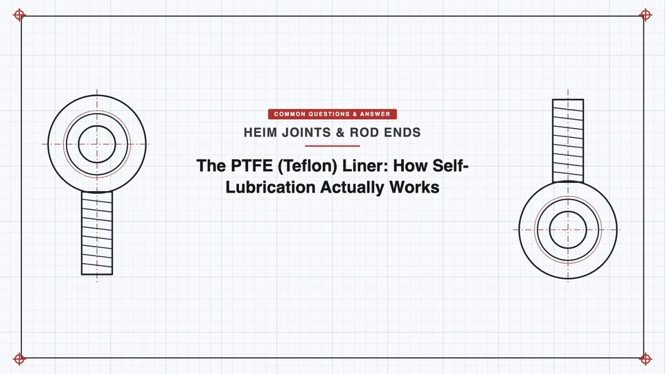
If you already know that a PTFE-lined rod end doesn’t need grease, this is the next question: how does a dry polymer liner keep a ball joint running smoothly for years without a drop of lubricant? The short answer is that it isn’t lubricating in the conventional sense at all — it’s building a self-renewing transfer film through a specific molecular mechanism, and the liner itself is a more engineered piece of hardware than "a Teflon coating" suggests. (For the basics — what self-lubrication means, the -65°F to +325°F operating range, the 0.05–0.10 friction coefficient against a hard-chrome ball — see our overview, What is a "self-lubricating" rod end? This piece picks up where that one leaves off.)
The Molecular Reason PTFE Slides So Easily
PTFE’s carbon backbone is fully shielded by fluorine atoms bonded through extremely strong carbon-fluorine covalent bonds — but the attraction between neighboring PTFE chains is weak. Under load, those chains shear past each other with very little resistance, the way one card slides across another in a deck rather than gripping it. That low interchain resistance is the entire basis for PTFE’s lubricity; it has nothing to do with a fluid film the way conventional grease does.
Transfer Film: The Mechanism That Actually Does the Lubricating
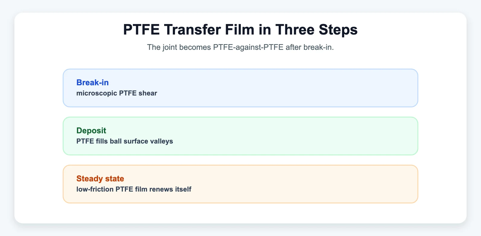
Here’s the part that’s easy to miss: a PTFE liner doesn’t lubricate by staying put. As the ball slides against it, microscopic surface asperities on the ball shear off tiny flakes of PTFE, which get pressed into the ball’s own microscopic surface valleys. Once that thin PTFE film establishes itself on the ball — typically during an initial break-in period — the joint is no longer running PTFE-against-metal. It’s running PTFE-against-PTFE, and because PTFE chains slip past each other so easily, friction drops and stays low for the working life of the liner. The film is consumed and continuously renewed as the liner wears, which is why the system keeps working without external lubricant: the liner is the lubricant reservoir, not a coating that eventually wears off and exposes bare metal underneath.
Friction coefficients reported for this system run from about 0.02 to 0.10, and — this is a detail most write-ups skip — the coefficient isn’t constant. According to NHBB’s (New Hampshire Ball Bearings, a MinebeaMitsumi aerospace-bearing subsidiary) engineering reference, friction decreases as load and temperature increase, but increases with faster sliding speed and rougher mating surfaces. That directionality matters for anyone speccing a rod end into a high-speed or high-vibration application — it isn’t a single fixed number regardless of operating conditions.
Why Pure PTFE Isn’t Used Alone
Pure (virgin) PTFE has excellent friction properties but poor wear resistance and a tendency to "cold flow" — creep and deform under sustained load. That’s why engineered liners are composites, not pure PTFE sheet. Common approaches include blending in glass fiber, bronze, carbon, graphite, or molybdenum disulfide to add load capacity and creep resistance while keeping the low-friction behavior largely intact.
How the Liner Is Actually Built
This is the piece most consumer-facing explainers skip entirely. NHBB’s engineering documentation on self-lubricating liner systems (developed originally for aerospace hardware, where liner reliability is safety-critical) describes four base construction types:
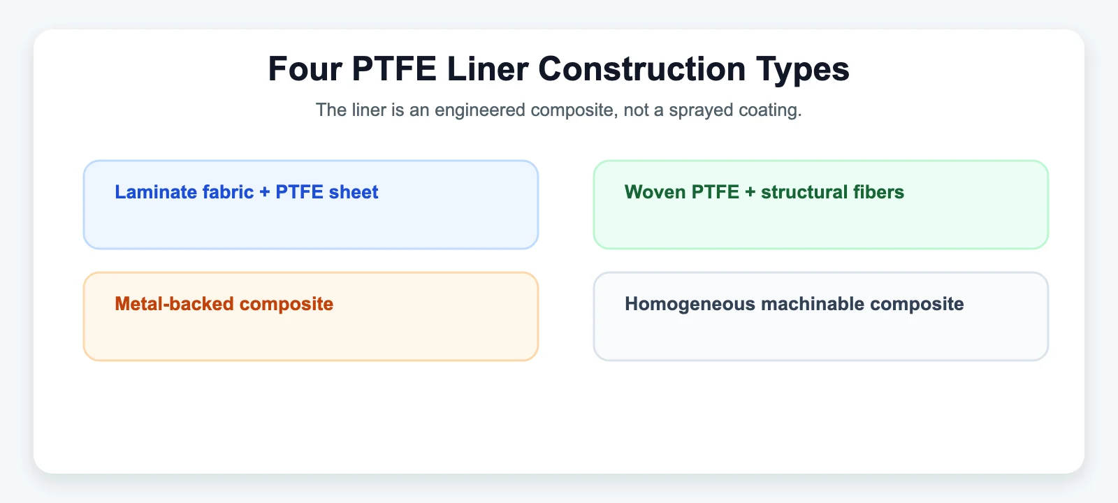
| Construction | How it’s built | Typical use case |
|---|---|---|
| Laminate | An open-weave backing fabric (e.g., nylon), a porous PTFE bearing sheet compressed into it, bonded with a thermosetting phenolic resin | Fixed/rotary wing aircraft control and actuation bearings |
| Woven | PTFE threads interwoven with high-strength fiber (nylon, polyester, or fiberglass); most PTFE ends up on the bearing surface, the fiber carries structural load and anchors the bond | Landing gear, rotary-wing pitch control bearings |
| Metallic-backed composite | Steel backing + porous bronze structure + PTFE/lead overlay; can be bonded or mechanically retained | Higher-temperature, higher-load applications |
| Homogeneous composite | A single machinable matrix of thermosetting resin, PTFE, and other compounds — fully machinable to final tolerance after bonding | Applications needing precise post-bond machining |
The common thread across all four: the PTFE layer is bonded to a metal race with a resin, not simply pressed or sprayed on. That bonding step is the technically difficult part of manufacturing a PTFE-lined rod end — PTFE’s molecular structure that makes it slippery to a ball also gives it very low surface energy, which makes it inherently hard to adhere to anything, including the backing fabric it needs to stick to. A liner that bonds poorly will delaminate from the race under load rather than wearing gradually, and liner separation is a sudden, not gradual, failure mode.
Surface Requirements on the Other Side of the Joint
A PTFE liner’s service life depends as much on the ball it’s riding against as on the liner itself. NHBB’s internal engineering guidance recommends a mating surface finish of 8 Ra or better (achieved by lapping, buffing, or honing) and a minimum hardness around Rc50 — below that, the mating surface itself starts to wear rather than just burnishing the liner. That hardness floor is well below what hard chrome plating delivers (63–72 HRC), which is part of why hard-chrome-plated balls and PTFE liners are paired as a matched system rather than either one being used interchangeably with an untreated surface. Note this specific 8 Ra / Rc50 figure is one aerospace-bearing manufacturer’s internal specification, not a universal rod end industry standard — different manufacturers may qualify their liners to different mating-surface tolerances.
How to Read Wear Over the Liner’s Service Life
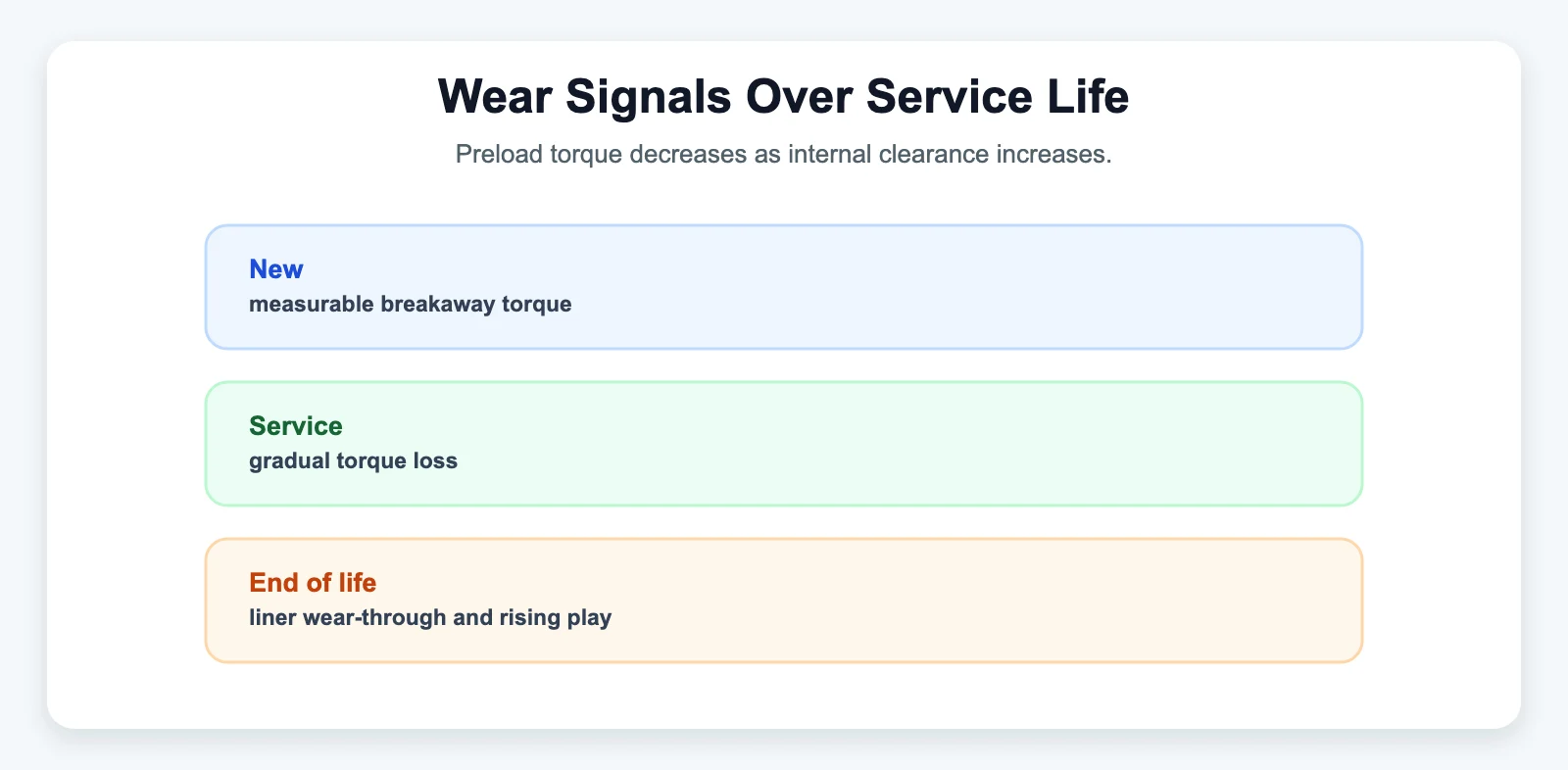
A PTFE-lined joint doesn’t fail the way a dry metal-to-metal joint fails. According to NHBB’s engineering reference, a new PTFE-lined bearing starts with a measurable rotational pre-load torque (the joint has a slight, specified resistance to rotation), and that pre-load decreases steadily with use while internal clearance increases steadily — the liner is slowly, microscopically conforming and wearing under compression. There’s a standardized way to measure this (Military Specification AS81820 describes a breakaway-torque test procedure), but the practical takeaway for anyone maintaining a fleet of rod ends is simpler: increasing radial or axial play over time is the liner’s way of telegraphing wear before it fails outright. A liner is generally considered at end of life once it wears through enough that the ball begins contacting the bare race — at that point, the joint reverts to unlubricated metal-to-metal contact and wear accelerates sharply.
Related reading: Hard Chrome Plating: How It Increases Rod End Service Life · Nylon Race vs. Metal-to-Metal: Choosing the Right Bearing Interface · What is a "self-lubricating" rod end? · Why Are Rod Ends and Spherical Bearings Teflon Lined?