Safety first: if you’re feeling the car pull or dart over bumps right now, that’s a steering geometry problem, not something to diagnose while driving at speed. Get an alignment check and inspect your tie rod ends and ball joints for play before making any changes below — a loose steering joint at highway speed is a separate and more urgent problem than bump steer itself.
Yes, high-misalignment spacers can be used to correct bump steer — but the spacer itself doesn’t fix the geometry. It solves a different, narrower problem: it lets a rod end keep articulating freely after you’ve moved its mounting point to a new height. The actual fix — relocating the outer tie-rod pivot so its arc more closely matches the lower control arm’s arc — is a separate step. Confusing the two is the most common mistake in this kind of build.
For the broader menu of bump steer fixes (geometry checks, worn-part replacement, professional alignment), see our general guide: How to Avoid Bump Steer. This article goes deep on one specific technique from that list.
Why a Standard Rod End Isn’t Enough
Bump steer happens when the tie rod and the lower control arm sweep through different arcs as the suspension travels — the mismatch shows up as unwanted toe change. The standard fix is to move the outer tie-rod pivot height so its arc lines up better with the control arm’s.
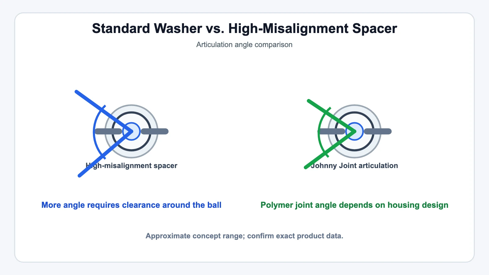
The problem: every rod end has a maximum misalignment angle — the angle the ball can rotate to before the shank contacts the housing and binds. Move a standard rod end’s mounting point far enough to fix your bump steer curve, and you can easily push it past that angle, especially at full suspension travel. A high-misalignment spacer is a specifically shaped bushing that sits in the rod end’s bore and gives the shank extra clearance to swing through a wider cone before it contacts anything — it’s what makes the relocated position mechanically usable, not what decides where that position should be.
Misalignment angle varies by product, and the numbers aren’t small. GKTECH’s high-misalignment tie rod end line, as one example, specs its PTFE-lined rose joints at 64° of misalignment versus roughly 60° for a typical OEM-style tie rod end, with up to 15 mm of bump steer correction built in via 5 mm shims and a shank rated to 176 ksi (class 12.9) tensile strength. These are one manufacturer’s published specs, not an industry standard — the actual misalignment range on any rod end you buy depends entirely on that specific product’s design, so check the manufacturer’s number rather than assuming "high misalignment" means a fixed angle.
The Adjustment Process
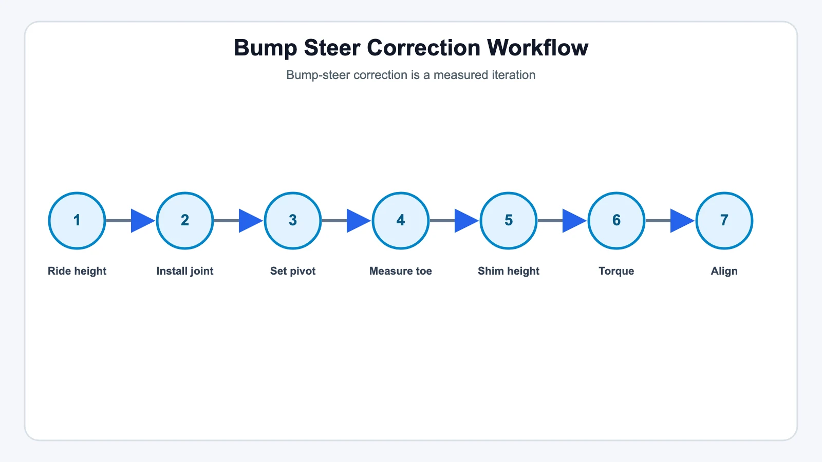
- Start at actual ride height. Bump steer correction is meaningless if measured with the car on a jack stand at the wrong height — get the suspension loaded the way it sits when driven.
- Remove the factory tie rod end and install the rod end/heim joint with high-misalignment spacers on both sides of the spherical bearing, per the manufacturer’s design.
- Set an initial pivot height — a reasonable starting point is close to where the tie rod and lower control arm sit at similar angles, but this is a starting guess, not a final answer.
- Measure, don’t guess. With a dial indicator against the wheel or rotor edge, record toe at ride height, then cycle the suspension roughly 1 inch into bump and 1 inch into droop, recording toe at each position.
- Adjust the spacer stack based on the direction of the error: if toe changes out under compression, most builders move the pivot down (add shims above the joint); if it changes in, move the pivot up. Repeat until toe change across the travel you actually use is minimized — a commonly cited target is under 0.030 in. total, though that’s a practical benchmark from suspension-tuning discussion, not a published factory tolerance.
- Torque to spec and lock it down — jam nuts or safety wire on the adjustment threads, not just friction.
- Finish with a professional alignment. Moving the tie-rod pivot changes toe and can shift camber slightly; don’t call the job done until an alignment tech has signed off on the final numbers.
There is no universal "use a 5 mm spacer" answer. The correct spacer thickness depends on your specific rack or steering-arm height, ride-height change, control-arm geometry, and how much suspension travel you actually use — a GKTECH kit’s published 5 mm shim result on a GT86 is that chassis’s number, not a rule for your build.
What Not to Do
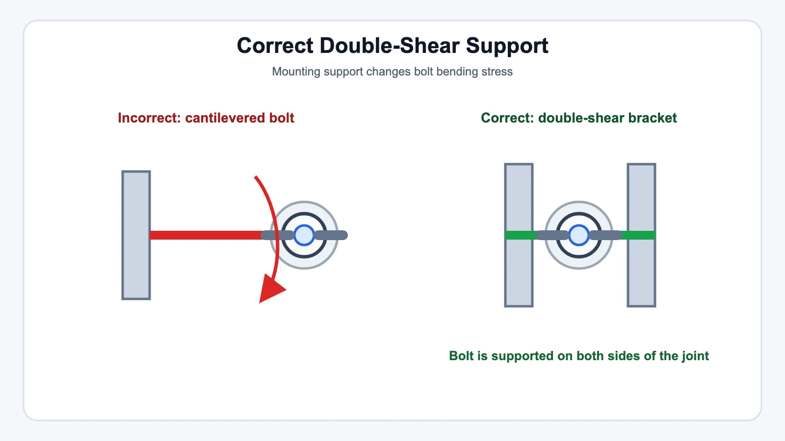
Don’t stack generic flat washers under a heim joint as an improvised spacer. A proper high-misalignment spacer is shaped to preserve the rod end’s articulation range and distribute load correctly; a stack of standard washers doesn’t do either, and can introduce bending loads into the steering knuckle or arm that the joint wasn’t designed to carry. Where the design allows it, double-shear mounting (the rod end captured on both sides rather than cantilevered off one bolt) is the more forgiving setup for a steering application.
A Real Build, and a Real Warning
A MINI Cooper (R53) owner documented exactly this process on the North American Motoring forum after lowering the car on coilovers: factory tie rods stayed at their original height while the lowered control arms pulled the geometry out of parallel, creating bump steer. The fix was a custom tie-rod assembly using a heim joint and a stack of spacing rings — after some trial and error, "took one spacing ring out and moved the heim joint up a hair, turns out this was the magic spot," with bump steer and steering-wheel vibration both noticeably reduced afterward.
The same thread carries a pointed warning from another user running a similar setup: "Keep a close watch on those heim joints for looseness — like every 200 or so miles. They don’t last long on the street, bearing covers or not." That’s one forum member’s personal maintenance habit, not a manufacturer-specified interval, but it reflects a real pattern worth taking seriously: an exposed heim joint on a street-driven tie rod sees far more contamination exposure than the same joint would in a dedicated race application, and it needs to be checked more often than a sealed OEM tie rod end would.
Where This Fits by Scenario
| Scenario | Typical need | Key consideration |
|---|---|---|
| Lowered street car | Move tie-rod pivot down to re-match control-arm arc | Correction is usually a fixed amount for a given drop — measure once, verify, done |
| Lifted off-road truck | Move tie-rod pivot up | Larger corrections may exceed a standard rod end’s misalignment range without a high-misalignment spacer |
| Race car with adjustable ride height | Re-verify at each height setting | Spacer stack that’s correct at one ride height may not be correct at another |
Related reading: How to Avoid Bump Steer · Understanding Instant Center and Roll Center in Suspension Design