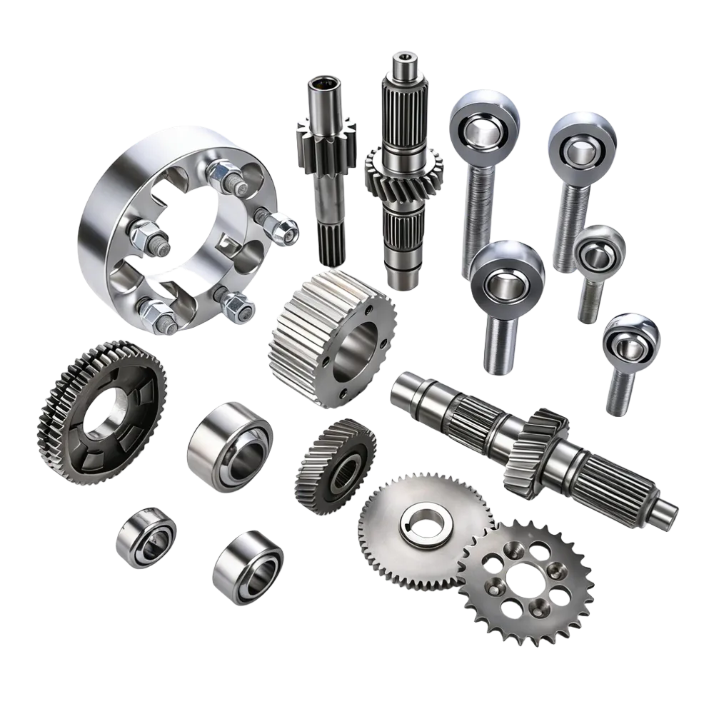
An interference fit — also called a press fit, force fit, or friction fit — is a shaft-and-hole combination where the shaft is always slightly larger than the hole, even at the loosest allowed tolerance combination. Assembling the two requires force, heat, or cold to elastically deform the parts as they go together; once assembled, the resulting contact pressure and friction hold the joint without any additional fastener.
How the Joint Actually Holds
Three things happen together:
- Dimensional overlap — the shaft’s outer diameter is manufactured slightly larger than the hole’s inner diameter before assembly.
- Elastic deformation — as the parts are forced together, the hole expands slightly and the shaft compresses slightly, each pushing back against the other.
- Friction lock — the resulting radial pressure creates a friction grip strong enough to resist both rotation and axial movement, without keys, adhesive, or fasteners.
Three Ways to Assemble One
- Mechanical pressing — pushing the shaft into the hole with an arbor press or hydraulic press. Used for lighter interference.
- Thermal expansion (shrink fitting) — heating the outer part so its bore expands, dropping the shaft in, then letting it cool and contract around the shaft.
- Cold/freeze fitting — cooling the inner part (shaft) so it contracts, inserting it into the hole, then letting it warm back up and expand to lock in place.
The Three Interference Fit Grades
From lightest to heaviest:
| Grade | Assembly method | Typical use |
|---|---|---|
| Press fit | Cold pressing | Hubs, bushings, bearings |
| Driving fit | Cold pressing (higher force) or hot pressing | Permanent mounting of gears, shafts, bushes |
| Forced fit | Requires heating the bored part and/or freezing the shaft | Highly stressed shaft/gear assemblies; disassembly usually damages the parts |
What the Interference Actually Looks Like (25 mm Worked Example)
Using the same 25 mm nominal diameter as a clearance-fit example, here’s how the interference range grows with fit grade:
| Fit designation | Grade | Min. interference | Max. interference |
|---|---|---|---|
| H7/p6 | Press fit | 0.001 mm | 0.035 mm |
| H7/s6 | Driving fit | 0.014 mm | 0.048 mm |
| H7/u6 | Forced fit | 0.027 mm | 0.061 mm |
Even the lightest interference fit (H7/p6) guarantees at least 0.001 mm of overlap at minimum material condition — that’s the defining property versus a transition fit, where the range can dip into clearance depending on where the actual parts land in tolerance.
These figures are illustrative for a 25 mm shaft/hole pair; the same fit designations scale to other diameters through the ISO 286 tolerance tables, but the absolute interference values shift with size.
Typical Applications
- Gears, pulleys, and bearings mounted directly onto a shaft
- Bushings pressed into a housing
- Any connection that needs to transmit rotational torque without relying on keys or fasteners
How This Connects to the Tolerance Codes on Your Print
The fit designations above (H7/p6, H7/s6, etc.) come from ISO 286 tolerance codes — a letter for the fundamental deviation (position of the tolerance zone relative to nominal size) and a number for the IT grade (width of the zone). If you’re decoding a specific callout like g5 or h7 on a drawing, see What Does a g5 Tolerance Mean on a Shaft? for how those codes work and how to read the deviation tables directly. And for the loose-fit end of the same spectrum, see What Is a Clearance Fit?.
Related reading: What Is a Clearance Fit? · What Does a g5 Tolerance Mean on a Shaft? (ISO Tolerance Codes Explained)