The geometry of tilt
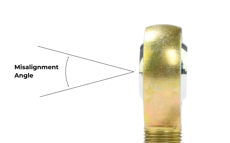
A standard rod end usually offers a misalignment angle between 12° and 22°. This angle is a direct result of the relationship between the ball’s diameter and the housing’s opening width.
- The Boundry: Once the joint reaches its mechanical limit, any further suspension movement creates a use effect. This is called “binding,” and it can multiply the forces on your mounting brackets by a factor of ten.
- Standard Compliance: Most precision joints are measured according to ISO 12240-4 standards to ensure that the stated misalignment angle is consistent across manufacturing batches.
How to increase your articulation
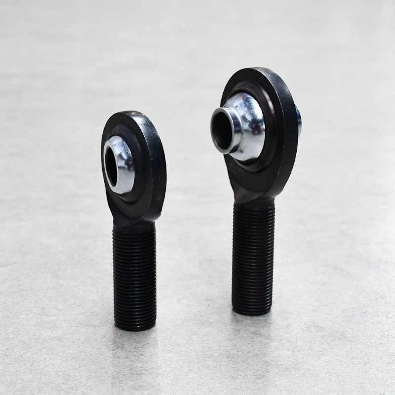
If your suspension design requires more travel than a standard Heim allows, you have two engineering options:
- High Misalignment Spacers: These reduce the bolt diameter and “thin out” the ball, allowing for angles up to 30° or 34°.
- Mounting Orientation: Rotating the axis of the joint 90 degrees (vertical vs. horizontal mounting) can often move the binding point outside of the suspension’s travel range.
Related reading: What is a “high misalignment” rod end? · Do You Always Need High-Misalignment Spacers? · High-Misalignment Limit: When to Use Bent Links Instead of Spacers