Thread size alone does not define a rod end. Two rod ends with an identical thread spec can differ in bore diameter, body width, and housing outside diameter by enough to prevent proper fit — which is exactly the mistake that produces the wrong custom part more often than any other. Ordering a non-standard rod end correctly means gathering seven to eight specific dimensions before you contact a manufacturer, not just describing the thread.
Why "Thread Size" Isn’t a Full Specification
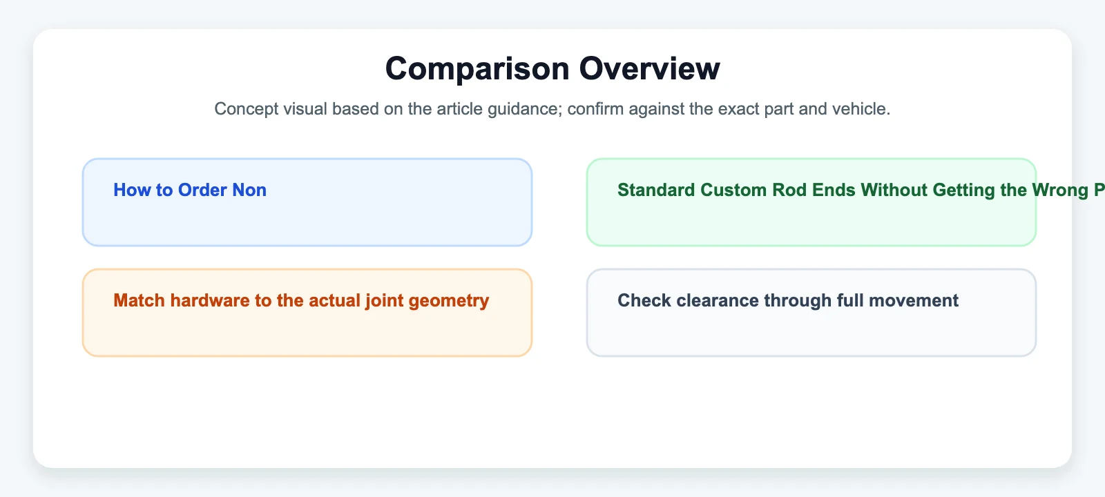
A rod end connects at two ends: the threaded shank attaches to your rod or tube, and the ball/bore assembly connects to the pivot. Thread size only describes the first connection. It tells a manufacturer nothing about how much axial space the joint occupies, whether the ball will clear surrounding structure at full articulation, or what pin diameter fits the bore. Ordering "a 1/2-20 rod end" without the rest of the dimensions leaves the manufacturer to apply their own defaults — which may not match what you actually need.
The Dimensions to Confirm Before You Contact a Manufacturer
Under ISO 12240-4, the industry dimensional standard for spherical plain bearing rod ends, each of these has a formal designation. Referencing the standard’s letter codes when you order gives a manufacturer an unambiguous target instead of a verbal description they have to interpret:
| Dimension | ISO 12240-4 designation | What to confirm |
|---|---|---|
| Bore diameter | d | Nominal size and tolerance class — H7 gives a close, low-play fit; H9 gives a looser fit acceptable for slow-pivot structural use but audible as knock in dynamic linkages. Two readings 90° apart that differ by more than 0.05 mm indicate an out-of-round worn part, not a valid reference for a new order. |
| Thread size, pitch, and hand | d3 (or G) | Metric as diameter × pitch (e.g., M12×1.75); inch as diameter-TPI with series (1/2-20 UNF vs. 1/2-13 UNC — same diameter, will not interchange). Thread hand (RH/LH) must be confirmed by physically threading into a known RH fitting, not assumed from appearance. |
| Inner ring width / body width | B / C | The ball’s axial thickness (B) versus the housing ring thickness (C) — both set the clearance needed inside your mounting clevis. |
| Housing outside diameter | d2 | Not standardized across manufacturers — two rod ends with the same thread size from different suppliers can have housing ODs differing by 2–3 mm. Measure the part you’re replacing directly if clearance is tight. |
| Center height | h (or l3) | Distance from bore center to the housing shoulder or shank base — the critical installation dimension for bracket fit. |
| Overall shank length / thread engagement length | l1 / l2 | Engagement length must be checked at the longest position your linkage will actually use, not the midpoint — a 1.5× nominal-thread-diameter minimum engagement is the standard rule of thumb, and it can fail at full extension even if it looks fine installed at rest. |
| Misalignment angle | — | Standard rod ends typically offer 12–18° of misalignment; high-misalignment configurations reach 25–34°. Running a joint beyond its rated angle causes edge loading on the liner, concentrating wear on one line of the ball surface instead of distributing it. |
A digital caliper with 0.01 mm (or 0.001 in) resolution is the tool that produces reliable readings for all of the above — a steel rule introduces enough parallax error to misread a bore by 0.5 mm, which is the difference between a snug pin fit and a sloppy one.
What to Send: Drawing or Sample, Not Just a Description
Across every source we checked, the same hierarchy holds:
- A CAD file (STEP or DXF) — the most unambiguous format, lets the manufacturer’s engineering team check fit and tolerances directly
- A dimensioned sketch — acceptable if it includes the critical tolerances (bore tolerance class, thread class), not just nominal numbers
- A worn or broken original part — usable for reverse engineering, but confirm which dimensions came from the worn part (unreliable — measure at two points 90° apart to check for out-of-round wear) versus the original design intent
Also specify: static vs. dynamic load requirement, operating temperature range, environment (corrosion/dirt/chemical exposure), and the bearing interface you want (PTFE-lined for self-lubricating, greasable metal-to-metal for serviceable applications you can purge and inspect).
A Usable RFQ Template
An RFQ that includes the following gives any manufacturer enough to quote accurately on the first pass, rather than a back-and-forth to fill gaps:
> Custom rod end request: [Male/Female] shank, [RH/LH] thread, [thread size and pitch]. Bore diameter [X mm/in], tolerance class [H7/H9]. Body width [X], housing OD [X], overall shank length [X], thread engagement required [X] at maximum linkage extension. Misalignment angle required: [X]°. Material: [chromoly/stainless/aluminum/etc.], liner: [PTFE-lined/metal-to-metal]. Load: [static/dynamic, magnitude if known]. Quantity: [N prototype units / N production units]. Attached: [CAD file / dimensioned drawing / sample photos]. Target delivery: [date]. Inspection requirements: [if critical — dimensional report, material cert, etc.].
The specificity matters more than the format — a manufacturer that receives bore tolerance class, engagement length at full extension, and a documented misalignment requirement doesn’t have to guess where your application’s actual failure risk sits.
How Manufacturers Typically Structure the Intake
As a documented example of how one manufacturer organizes this process (not a recommendation that this is the only or best approach), SYZ Machine’s heim joint page describes a three-step custom intake: submit thread size, bore, material, finish, liner/race, mounting width, misalignment angle, target quantity, and any drawing or sample photos; receive a quote and production-route recommendation; then a single point of contact carries the order through confirmation, manufacturing, inspection, and shipping. The information requested lines up directly with the dimension checklist above — which is itself a useful check on whether a manufacturer you’re evaluating is asking the right questions, regardless of which supplier you choose.
The Cost of Skipping This
An order placed on thread size alone typically comes back either wrong (housing interferes with the bracket, misalignment angle is insufficient, thread engagement is too short at full extension) or over-specified defensively by the manufacturer to avoid liability — neither outcome is what a buyer with a genuinely non-standard requirement wants. The seven-dimension checklist above, backed by a drawing or sample, is what turns "custom" from a source of back-and-forth delay into a single accurate quote.
Related reading: Why Choose SYZ Machine Custom Chromoly Heim Joints? · Why High-Precision Rod Ends Have Longer Lead Times · Minimum Order Quantities (MOQ) for Custom Production Runs