How to identify thread direction
Mixing up thread directions is a common assembly error. At SYZ, we follow industry standards for clear identification:
- LH Identification: Left-hand joints are marked with a machined groove or notch on the shank or the hex area.
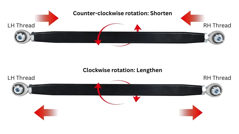
- The Turnbuckle Logic: If you turn a bump steer kit tube with an RH joint on one end and an LH on the other, both joints will either move inward (shortening) or outward (lengthening) simultaneously.
Safety and thread engagement
Proper thread engagement is non-negotiable for safety.
- The 1.5x Rule: As a general engineering guideline, thread engagement length should be at least 1 to 1.5 times the male thread diameter. Softer materials, aluminum adapters, or high-load suspension and steering applications should use the higher end of that range. Always follow the vehicle builder’s or component manufacturer’s specification when one is available.
- Hardware Matching: An LH joint must be paired with an LH jam nut and an LH weld-in bung or tube adapter. Attempting to force a RH nut onto an LH joint will damage or strip the threads.
Related reading: Using LH/RH Threads for Quick Linkage Adjustments · Fine-Tuning Toe-In Without Disassembling Your Linkage · What are bung adjuster nuts and how to use them?