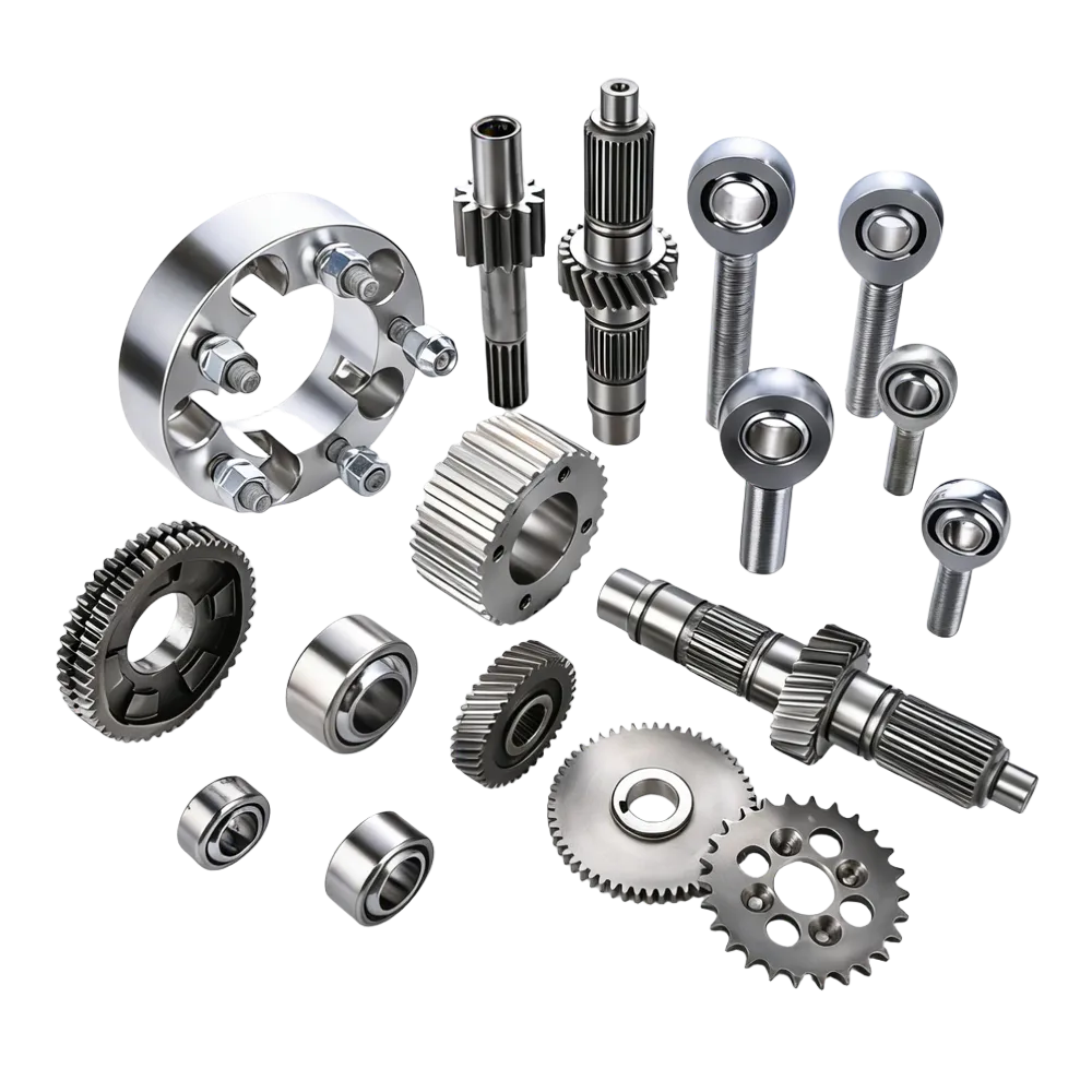
A threaded insert is a small fastening component that creates a strong, reusable internal thread inside a material that can’t reliably hold a thread on its own — soft metal, plastic, wood, or a 3D-printed part. Instead of cutting a thread directly into the base material, you install the insert into a prepared hole, and the insert provides the actual thread the screw or bolt engages. Using one correctly comes down to three things: picking the right type for your material, preparing the hole to the right size, and installing it straight.
The Main Types and What They’re For
| Type | How it locks into the material | Typical base material | Typical use |
|---|---|---|---|
| Wire/coil thread insert (Heli-Coil style) | Coiled wire form, installed into a hole pre-tapped with a special STI tap | Metal (aluminum, soft metals) | Repairing stripped threads, reinforcing threads in soft metal |
| Self-tapping insert | External cutting features that form their own thread as it’s driven in | Aluminum, soft metals, engineering plastics | General mechanical assembly, thread repair, no pre-tapping needed |
| Heat-set insert | Heated and pressed in; surrounding plastic melts and flows around it, then cools and locks it in place | Thermoplastics, 3D-printed parts | Electronics housings, printed brackets, anything reassembled repeatedly |
| Wood insert | Coarse external thread that bites into wood fiber as it’s turned in | Wood, plywood, MDF | Jigs, fixtures, furniture-style assemblies |
| Key-locking insert | Solid insert with locking keys driven in after installation to resist rotation | Metal, high-vibration joints | High-strength repair, vibration-prone assemblies |
These aren’t interchangeable — the right choice depends on what you’re installing it into, not just what thread size you need.
The General Installation Process
- Identify the base material. Metal, wood, and plastic each need a different insert design and preparation method — a wood insert and a metal self-tapping insert aren’t installed the same way, even if both end up with the same internal thread size.
- Match the internal thread to your screw or bolt. Common sizes run from small (M3) up through larger structural sizes (M10-M12 and beyond) depending on the application.
- Prepare the hole to the correct size. This is the step most installation failures trace back to — see below.
- Keep the insert straight (perpendicular to the surface) during installation. A crooked insert produces a crooked screw path, which matters even in non-precision work and matters a lot in anything requiring alignment.
- Install with controlled, steady force — don’t rush a self-tapping insert, don’t overheat a heat-set insert, don’t force a wood insert fast enough to split the fibers.
- Test the fit by threading the actual screw or bolt in afterward — it should engage smoothly without wobble or binding.
Why the Pilot Hole Is the Detail That Decides Success or Failure
Across metal, plastic, and wood installations, the size of the prepared hole is the single most common point of failure. A hole that’s too small can crack the surrounding material, deform the insert, or damage its external cutting structure. A hole that’s too large lets the insert spin under torque, lose pull-out strength, and eventually work loose — especially under vibration.
As a reference point, one fastener manufacturer’s engineering guide publishes the following starting values for self-tapping metal inserts:
| Internal Thread | Insert OD | Insert Length | Reference Pilot Hole Ø | Reference Pilot Hole Depth |
|---|---|---|---|---|
| M3 | 5.0 mm | 6 mm | 4.6–4.8 mm | 8 mm |
| M4 | 6.5 mm | 8 mm | 6.0–6.2 mm | 10 mm |
| M5 | 8.0 mm | 10 mm | 7.3–7.6 mm | 12 mm |
| M6 | 10.0 mm | 14 mm | 8.9–9.4 mm | 16 mm |
| M8 | 12.0 mm | 15 mm | 10.9–11.4 mm | 17 mm |
| M10 | 14.0 mm | 18 mm | 12.9–13.4 mm | 20 mm |
| M12 | 16.0 mm | 22 mm | 14.9–15.4 mm | 24 mm |
The source of this table is explicit that these are engineering starting points, not universal rules — values vary by insert series, manufacturer, base material, and installation method, and should always be checked against the actual product datasheet before production use. Treat this table the same way: a reference for what range to expect, not a substitute for your specific insert’s spec sheet.
Installation Notes by Material
Metal. The priorities are correct drill size, chamfering the hole opening, removing burrs and chips, and keeping the insert perpendicular. Metal inserts are especially useful in aluminum, where repeated screw removal wears out the original threads faster than in steel — an insert restores a damaged hole without replacing the part.
Wood. Use a pilot hole sized for the specific insert (wood insert manufacturers publish this), avoid placing the insert too close to an edge (risk of splitting), and drive it in slowly. Performance depends heavily on wood type and grain direction — a hole that works fine in hardwood can split softwood or grip poorly in MDF, so testing on scrap material first is worthwhile with an unfamiliar material.
Plastic. Wall thickness around the insert matters as much as the insert itself — a thin, unsupported wall can crack even with a correctly sized insert. For heat-set inserts specifically, controlling installation temperature matters: too much heat deforms the surrounding plastic boss, too little prevents the insert from seating and locking properly.
A Threaded Insert Doesn’t Replace Vibration-Resistant Design
It’s worth being direct about a common misunderstanding: a threaded insert strengthens the thread itself, but it doesn’t automatically stop a screw from loosening under vibration. In assemblies that see ongoing vibration, you still need the same anti-loosening measures you’d use in any threaded joint — appropriate preload, washers, thread-locking compound, or a locking hardware design. The insert solves “the base material can’t hold a thread reliably.” It doesn’t solve “vibration works fasteners loose” on its own.
Common Installation Mistakes
- Wrong pilot hole size — the single most frequent cause of failure, in either direction (too tight or too loose).
- Crooked installation — throws off alignment for anything downstream of the screw path.
- Insufficient surrounding material support — especially relevant in plastic and thin-wall parts, where the wall around the insert needs enough thickness to hold up under load.
- Overheating (heat-set inserts specifically) — deforms the part instead of properly seating the insert.
- Over-tightening the mating screw — the insert may be metal, but the parent material still has real strength limits; excessive torque can crack plastic, crush wood, or damage soft metal around the insert.
How This Relates to Bungs in Tube Fabrication
Threaded inserts and bungs solve the same underlying problem — putting a reliable thread into a material that can’t hold one directly — but they’re not the same part. A bung is the tube-fabrication-specific version of this idea: a welded-in threaded sleeve sized for a rod end or heim joint in suspension and chassis tube work. If that’s the application you’re actually working on, see What Are Bungs? for the fabrication-specific version of this topic.
What Wasn’t Found
The research gathered for this question returned general fastening and mechanical-assembly sources (woodworking, 3D printing, general industrial hardware) rather than anything specific to automotive tube fabrication — which is expected, since “threaded insert” is a broad fastening term used well beyond that one application. No source provided sizing data specific to off-road suspension or chassis tube work; for that application, refer to the bung-specific article linked above.
Related reading: What Are Bungs? The Threaded Tube Insert Every Fabricator Should Know